| Quantity: | |
|---|---|
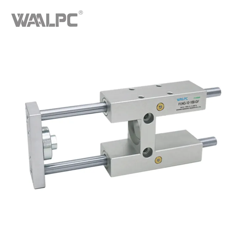
FENG-GF/KF
WAALPC
8409919990
ORDERING CODE

SPECIFICATION
| Model | XEN-... |
XENG-... | ||||||||
| BoreΦ | 8/10 | 12/16 | 20 | 25 | 32 | 40 | 50 | 63 | 80 | 100 |
| Stroke(mm) | 1...100 | 1...200 | 1...200 | 1...500 | ||||||
| Guide | Plain-bearing Guide | |||||||||
| Installation | Recirculating Ball | |||||||||
| Installation position | Any | |||||||||
| Operating Range Temperature | -20~+80℃ | |||||||||
OVERALLDIMENSION&STRUCTURE
FEN 12~16

FEN 20~25
*In ( ) is the size of 25

FENG 32~100

| Bore(mm) | J | Q | W | P | S | T | U | ΦZ | ΦY | V | L1 | O | D | E |
| 32 | 67+0.5 | 50.5±0.3 | 32.5±0.2 | 78±0.2 | 90 | 70.3±0.2 | 78±0.2 | 11 | 6.5 | 6.5 | 155 | 14 | M6 | 12 |
| 40 | 75+0.5 | 58.5±0.3 | 38±0.2 | 16±0.2 | 110 | 84±0.2 | - | 11 | 6.6 | 6.5 | 170 | 17 | M6 | 14 |
| 50 | 89+1.0 | 70.5±0.3 | 56.5±0.2 | 20±0.2 | 130 | 81.8±0.2 | 100±0.2 | 13 | 9 | 9 | 188 | 22 | M8 | 16 |
| 63 | 89+1.0 | 85.5+0.3 | 56.5±0.2 | 20±0.2 | 145 | 105±0.2 | - | 13 | 9 | 9 | 220 | 22 | M8 | 16 |
| 80 | 111+1.0 | 106±0.6 | 72±0.2 | 25±0.2 | 180 | - | - | 18 | 11 | 11 | 258 | 27 | M10 | 20 |
| 100 | 111+1.0 | 131±0.6 | 89±0.2 | 25±0.2 | 200 | - | - | 18 | 11 | 11 | 263 | 27 | M10 | 20 |
| Bore(mm) | A | B | C | ΦR | F | KK | L | K | M | G | H | I | N |
| 32 | 50-0.3 | 97-0.4 | 61±0.2 | 12 | 74±0.2 | M10X1.25 | 125 | 24 | 76 | 12 | 20 | 4.3 | 45 |
| 40 | 58-0.3 | 115-0.4 | 69±0.2 | 16 | 87±0.2 | M12X1.25 | 140 | 28 | 81 | 12 | 22 | 11 | 54 |
| 50 | 70-0.3 | 137-0.5 | 85±0.2 | 20 | 104±0.2 | M16X1.5 | 150 | 34 | 79 | 15 | 25 | 18.8 | 63 |
| 63 | 85-0.3 | 152-0.1 | 100±0.2 | 20 | 119±0.2 | M16X1.5 | 182 | 34 | 111 | 15 | 25 | 15.3 | 80 |
| 80 | 105-0.3 | 189-0.5 | 130±0.2 | 25 | 147.5±0.2 | M20X1.5 | 215 | 40 | 128 | 20 | 32 | 21 | 100 |
| 100 | 130-0.3 | 213-0.5 | 150±0.2 | 25 | 172±0.2 | M20X1.5 | 220 | 40 | 128 | 20 | 32 | 24.5 | 120 |


