Views: 0 Author: Site Editor Publish Time: 2025-07-01 Origin: Site
A reliable and clean compressed air supply is the lifeblood of pneumatic systems across countless industries. While the air compressor generates the essential power, the quality of this air directly impacts equipment performance, lifespan, and operational costs. This is where Air Preparation Units (APUs), commonly referred to as FRL Units (Filter-Regulator-Lubricator), become indispensable. Properly installed and applied FRLs protect downstream equipment, ensure consistent operation, and maximize the efficiency of the entire compressed air system originating from the compressor.
Air drawn into a compressor contains contaminants:
Water Vapor: Condenses into liquid water within pipes.
Atmospheric Dirt & Dust: Abrasive particles.
Oil Vapor/Aerosols: From the compressor's lubrication or ambient oil mist.
Pressure Fluctuations: Compressor output isn't perfectly steady.
Unfiltered air causes:
Corrosion of pipes, valves, and cylinders.
Wear and scoring of seals and moving parts.
Malfunction of sensitive valves and instruments.
Inconsistent actuator speed/force due to pressure variations.
Contamination of end products (e.g., painting, food processing).
F - Filter (Air Filter):
Function: Removes liquid water, oil aerosols, and solid particles (dirt, rust) from the compressed air stream. Coalescing filters trap tiny oil/water droplets which merge and drain away.
Key Specs: Filtration rating (microns), flow capacity, condensate drain type (manual, semi-auto, auto).
R - Regulator (Air Pressure Regulator):
Function: Reduces and maintains a constant, pre-set downstream air pressure regardless of fluctuations in upstream pressure (from the compressor or varying demand).
Key Specs: Pressure range, flow capacity, relieving vs. non-relieving type, accuracy.
L - Lubricator (Air Line Lubricator):
Function: Introduces a fine mist of oil vapor into the air stream to lubricate downstream pneumatic components (cylinders, valves, tools). Note: Not always required, especially in oil-free systems or specific applications like food/pharma.
Key Specs: Oil capacity, drip rate adjustment, type of oil (ISO VG32 common).
Correct installation is paramount for effectiveness:
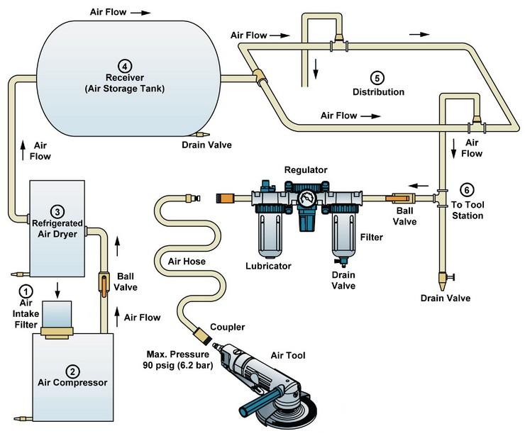
Location: Immediately After the Receiver Tank:
The air receiver tank acts as a primary cooler and moisture separator. Installing the FRL after the tank allows it to handle air that has already undergone some initial cooling and condensation. This is the most critical placement rule. Never install an FRL before the receiver tank.
The order must be: F -> R -> L (Filter -> Regulator -> Lubricator).
Filter First: Contaminants must be removed before reaching the Regulator and Lubricator to prevent damage and clogging of these precision components.
Regulator Second: Pressure must be stabilized before the Lubricator. Lubricators are calibrated for specific downstream pressures; upstream fluctuations would cause inconsistent oil misting.
Lubricator Last: Oil mist is introduced just before the air reaches the components needing lubrication.


Mounting Options:
Directly at the Compressor/Receiver Outlet: (Most common for central systems) Mounted securely on a wall, panel, or bracket near the compressor/receiver. Use sturdy brackets.
Modular Mounting:
Individual F, R, L components mounted onto a common manifold block for compactness and ease of piping.
Remote Mounting (Sub-Distribution):
Large systems may have a main FRL near the compressor/receiver and smaller FRLs (often just FR units) closer to specific machines or workstations to handle local pressure requirements and final filtration. Ensure the main FRL still protects the main distribution piping.
Piping Connections:
Use pipe sizes at least equal to the FRL's inlet/outlet ports to avoid unnecessary pressure drop.
Ensure piping is clean and debris-free before connection. Use thread sealant (PTFE tape or liquid) appropriately on threaded ports, avoiding entry into the air stream.
Support piping adequately to prevent stress on the FRL unit.
Condensate Drain Management (Filter):
Install the filter vertically with the bowl down, as designed.
Ensure the drain port is accessible and has sufficient clearance below it for drainage.
Connect auto/semi-auto drains to a proper condensate drain line leading to a safe disposal point. Never plug the drain!
Pressure Gauge:
The regulator typically has a gauge port. Install a pressure gauge here to accurately monitor and set the downstream pressure.
Lubricator Setup:
Fill with the correct pneumatic oil (as specified by component manufacturers).
Adjust the drip sight glass (usually a few drops per minute visible in the sight feed) only after the system is pressurized and air is flowing to downstream equipment. Start low and adjust based on component needs and distance.
The air compressor provides the power, but the FRL unit ensures its quality and usability. Proper installation – crucially, after the receiver tank and in the strict Filter -> Regulator -> Lubricator sequence – is fundamental. Correct application and diligent maintenance of the FRL unit are not just best practices; they are essential investments that protect valuable downstream pneumatic equipment, guarantee consistent system performance, improve energy efficiency, and significantly reduce operational downtime and costs. Never underestimate the critical role of air preparation in realizing the full potential of your compressed air system.