| Quantity: | |
|---|---|
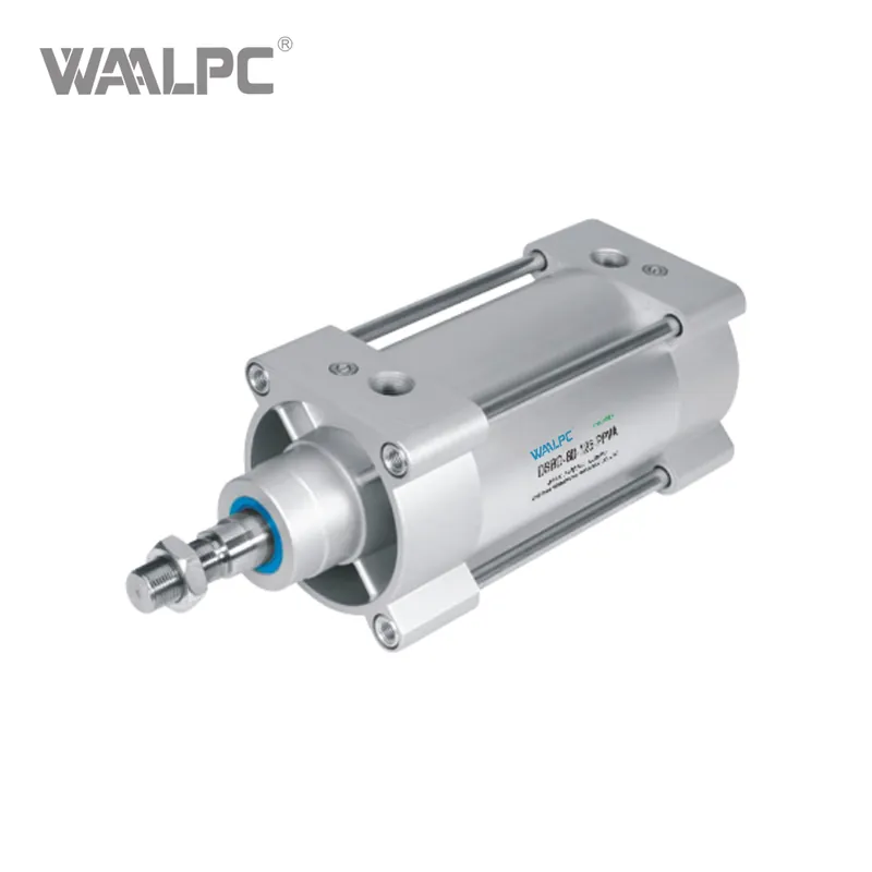
DSBG
WAALPC
8409919990
ORDERING CODE

SPECIFICATION
| Bore(mm) | 32 | 40 | 50 | 63 | 80 | 100 | 125 | ||
| Constructional design | Piston/Pistonrod/Profile barrel | ||||||||
| Action type | Double acting | ||||||||
| Pneumatic connection |
G1/8 | G1/4 | G1/4 | G3/8 | G3/8 | G1/2 | G1/2 | ||
| Stroke | DSBG-...[mm] |
1...2800 |
|||||||
| DSBG-...-Q[mm] | 1...1500- | - | |||||||
| DSBG-...-L1[mm] | 10...1000 | ||||||||
| DSBG-...-P2[mm] | 10...500- |
- | |||||||
| DSBG-...-...E[mm] | 1...2000 | ||||||||
| DSBG-...-...L[mm] | 1...2000 | ||||||||
| Cushioning | DSBG-...-P | Elastic cushions at both ends | |||||||
| DSBG-...-PPV | Adjustable pneumatic cushioning at both ends |
||||||||
| DSBG-...PPS | Self-adjusting pneumatic cushioning at both ends |
||||||||
| Cushioning length | DSBG-...-PPV[mm] |
17 |
19 | 22 | 22 | 31 | 31 | 45 | |
| Position sensing | Sensing via proximity switch | ||||||||
| Type of mounting | Via internal thread/attachment | ||||||||
| Mounting position | Arbitrary | ||||||||
OVERALLDIMENSION&STRUCTURE


| Φ(mm) | A -0.5 |
B Φ d11 |
BG Min. |
E +0.5 |
EE | G -0.2 |
U2 ±0.1 |
U1 ±0.1 |
KK | L2 | L3 Max. |
L7 ±0.4 |
L8 |
| 32 | 22 | 30 | 16 | 45 | G1/8 | 28 | 5.7 | 5.25 | M10x1.25 | 18-0.2 | 5 | 6.5 | 94 |
| 40 | 24 | 35 | 16 | 54 | G1/4 | 33 | 8 | 4 | M12x1.25 | 21.3-0.2 | 5 | 7.5 | 105 |
| 50 | 32 | 40 | 16 | 64 | G1/4 | 33 | 104 | 5.5 | M16x1.5 | 26.8-0.2 | 5 | 7.5 | 105 |
| 63 | 32 | 45 | 16 | 75 | G3/8 | 40.5 | 12.75 | 6.25 | M16x1.5 | 27-0.2 | 5 | 9 | 121 |
| 80 | 40 | 45 | 17 | 93 | G3/8 | 43 | 12.5 | 8 | M20x1.5 | 34.2-0.2 | - | 11 | 128 |
| 100 | 40 | 55 | 17 | 110 | G1/2 | 48 | 13.5 | 10 | M20x1.5 | 38-0.2 | - | 7.5 | 138 |
| 125 | 54 | 60 | 20 | 136 | G1/2 | 44.7 | 13 | 8 | M27x2 | 45-0.3 | - | 10 | 160 |
| Φ(mm) | MM Φ |
PL ±0.1 |
RT | TG ±0.3 |
VA | VD +0.5 |
WH +2.2 |
ZJ +1.8 |
ZM +1 |
|||
| 32 | 12 | 19.5 | M6 | 32.5 | 4-0.2 | 10 | 25 | 119.1 | 146.1 | 10 | 16 | 6 |
| 40 | 16 | 22.5 | M6 | 38 | 4-0.2 | 10.5 | 28.7 | 133.9 | 164.8 | 13 | 18 | 6 |
| 50 | 20 | 22.5 | M8 | 46.5 | 4-0.2 | 11.5 | 35.6 | 141.8 | 179.8 | 17 | 24 | 8 |
| 63 | 20 | 27.5 | M8 | 56.5 | 4-0.2 | 15 | 35.9 | 157.1 | 195.4 | 17 | 24 | 8 |
| 80 | 25 | 30 | M10 | 72 | 4-0.2 | 15.7 | 45.4 | 173.6 | 221 | 22 | 30 | 6 |
| 100 | 25 | 31.5 | M10 | 89 | 4-0.2 | 19.2 | 49.3 | 187.5 | 238.8 | 22 | 30 | 6 |
| 125 | 32 | 22.5 | M12 | 110 | 6-0.3 | 20.5 | 64.1 | 225 | 290 | 27 | 41 | 8 |


